 Hyundai Azera: Repair procedures
| Inspection |
Front Door Lock Actuator Inspection
| 1. |
Remove the front door trim.
|
| 2. |
Remove the front door module. |
| 3. |
Disconnect the 7P connector from the actuator.
|
| 4. |
Check actuator operation by connecting power and ground
according to the table. To prevent damage to the actuator, apply battery
voltage only momentarily.
|
Rear Door Lock Actuator Inspection
| 1. |
Remove the rear door trim.
|
| 2. |
Remove the rear door module. |
| 3. |
Disconnect the 7P connector from the actuator.
|
| 4. |
Check actuator operation by connecting power and ground
according to the table. To prevent damage to the actuator, apply battery
voltage only momentarily.
|
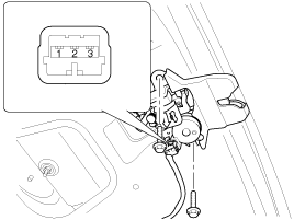
Trunk Lid Release Actuator Inspection
| 1. |
Remove the trunk lid trim panel.
|
| 2. |
Disconnect the 3P connector from the actuator.
|
| 3. |
Check actuator operation by connecting power and ground
according to the table. To prevent damage to the actuator, apply battery
voltage only momentarily.
|
Front Door Lock Switch Inspection
| 1. |
Remove the front door trim panel.
|
| 2. |
Remove the front door module. |
| 3. |
Disconnect the 6P connector from the actuator.
|
| 4. |
Check for continuity between the terminals in each switch position when inserting the key into the door according to the table.
|
Rear Door Lock Switch Inspection
| 1. |
Remove the rear door trim panel.
|
| 2. |
Remove the rear door module. |
| 3. |
Disconnect the 7P connector from the actuator.
|
| 4. |
Check for continuity between the terminals in each switch position according to the table.
|
Trunk Lid Open Switch Inspection
| 1. |
Remove the trunk lid trim.
|
| 2. |
Disconnect the 3P connector from the actuator.
|
| 3. |
Check for continuity between the terminals in each switch position according to the table.
|
Door Switch Inspection
Remove the door switch and check for continuity between the terminals.


Hood Switch Inspection
| 1. |
Disconnect the connector from the hood switch (A).
|
| 2. |
Check for continuity between the terminals and ground according to the table.
|
Burglar Horn Inspection
| 1. |
Remove the burglar horn (A) after removing 1 bolt and disconnect the 2P connector from the burglar horn.
|
| 2. |
Test the burglar horn by connecting battery power to the terminal 1 and ground the terminal 2. |
| 3. |
The burglar horn should make a sound. If the burglar horn fails to make a sound replace it. |
 Description and Operation
Description
Remote Keyless Entry System
The described function is a radio-frequency remote control
for central doors locking / unlocking, trunk release and Panic activity
of an automotive vehi ...
 Transmitter Specifications
Specification
ItemDescriptionPower source3VOperating temperature-20°C ~ +60°CRF ModulationFSKRF frequency433.92MHzBattery1EA (CR2032)
An inappropriately disposed battery ca ...
See also:
ETC (Electronic Throttle Control) System Schematic Diagrams
Circuit Diagram
...
Side Body Body Repair
Side Body A
Front side member tooling hole (O20)Fender apron upper member tooling hole (O10) Front door upper hinge mounting hole(O13) Front door lower hinge mounting hole (O13) Rear door upper h ...
Sunvisor
Use the sunvisor to shield direct light through the front or side windows. To
use a sunvisor, pull it downward. To use a sunvisor for a side window, pull it downward,
unsnap it from the bracket ...
Categories
Hyundai Azera Manuals
© 2011-2025 Copyright www.hgmanual.com


