 Hyundai Azera: Power Door Lock Actuators Repair procedures
Fifth generation HG (2011–2025) / Hyundai Azera 2011-2025 Service Manual / Body Electrical System / Power Door Locks / Power Door Lock Actuators Repair procedures
Fifth generation HG (2011–2025) / Hyundai Azera 2011-2025 Service Manual / Body Electrical System / Power Door Locks / Power Door Lock Actuators Repair procedures
| Inspection |
Front Door Lock Actuator Inspection
| 1. |
Remove the front door trim.
|
| 2. |
Remove the front door module. |
| 3. |
Disconnect the connector (7P) from the actuator.
|
| 4. |
Check actuator operation by connecting power and ground
according to the table. To prevent damage to the actuator, apply battery
voltage only momentarily.
|
Rear Door Lock Actuator Inspection
| 1. |
Remove the rear door trim.
|
| 2. |
Remove the rear door module. |
| 3. |
Disconnect the connector (7P) from the actuator.
|
| 4. |
Check actuator operation by connecting power and ground
according to the table. To prevent damage to the actuator, apply battery
voltage only momentarily.
|
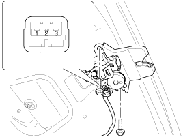
Trunk Lid Release Actuator Inspection
| 1. |
Remove the trunk lid trim panel.
|
| 2. |
Disconnect the 3P connector from the actuator.
|
| 3. |
Check actuator operation by connecting power and ground
according to the table. To prevent damage to the actuator, apply battery
voltage only momentarily.
|
Front Door Lock Switch Inspection
| 1. |
Remove the front door trim panel.
|
| 2. |
Remove the front door module. |
| 3. |
Disconnect the 6P connector from the actuator.
|
| 4. |
Check for continuity between the terminals in each switch position when inserting the key into the door according to the table.
|
Rear Door Lock Switch Inspection
| 1. |
Remove the rear door trim panel.
|
| 2. |
Remove the rear door module. |
| 3. |
Disconnect the 7P connector from the actuator.
|
| 4. |
Check for continuity between the terminals in each switch position according to the table.
|
Trunk Lid Open Switch Inspection
| 1. |
Remove the trunk lid trim.
|
| 2. |
Disconnect the 3P connector from the actuator.
|
| 3. |
Check for continuity between the terminals in each switch position according to the table.
|
 Components and Components Location
Component Location
1. Driver power window switch2. Door lock switch3. IPM(Intelligent intergrated Platform Module)4. Front door lock actuator5. Rear door lock actuator6. Trunk lid open actuator7. ...
 Power Door Lock Switch Repair procedures
Inspection
Diagnosis With GDS
1.
It will be able to diagnose defects of DDM/ADM with GDS
quickly. GDS can operates actuator forcefully, input/output value
monitoring and self diagnosis.
2. ...
See also:
CVVT (Continuously Variable Valve Timing) System Description and Operation
Description
Continuous Variable Valve Timing (CVVT) system advances or
retards the valve timing of the intake and exhaust valve in accordance
with the ECM control signal which is calculated by ...
Front Hub - Axle Components and Components Location
Components
1. Coking nut2. Brake disc3. Hub4. Dust cover5. Knuckle6. Wheel bearing7. Snap ring8. Drive shaft
...
Timing Chain Repair procedures
Removal
1.
Set No.1 cylinder to TDC/compression.
(1)
Turn the crankshaft pulley clockwise and align its groove with the timing mark "T" of the lower timing chain cover.
(2)
Check that the m ...
Categories
Hyundai Azera Manuals
© 2011-2025 Copyright www.hgmanual.com


