 Hyundai Azera: Power Out Side Mirror Switch Repair procedures
Fifth generation HG (2011–2025) / Hyundai Azera 2011-2025 Service Manual / Body Electrical System / Power Door Mirrors / Power Out Side Mirror Switch Repair procedures
Fifth generation HG (2011–2025) / Hyundai Azera 2011-2025 Service Manual / Body Electrical System / Power Door Mirrors / Power Out Side Mirror Switch Repair procedures
| Inspection |
| 1. |
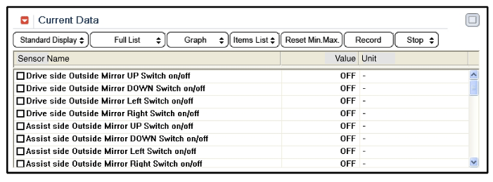
The DDM inputs can be checked using the GDS. |
| 2. |
To check the input value of door lock switch, select option "IPM". |
| 3. |
Select option "DDM (Driver Door Module)". |
| 4. |
Select option "Input/Output monitoring".
|
| 5. |
To check the input value of door lock switch in force mode, select option "ACTUATION TEST".
|
| Removal |
| 1. |
Disconnect the negative(-) battery terminal. |
| 2. |
Remove the front door trim panel.
|
| 3. |
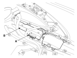
Disconnect the power window switch module connector (A) from the wiring harness.
|
| 4. |
Remove the power window switch module (B) from the door trim after loosening the mounting screws. |
| Installation |
| 1. |
Install the power window switch module. |
| 2. |
Install the door trim panel after reconnecting the relevant connectors
|
 Power Door Mirror Actuator Repair procedures
Inspection
1.
Remove the front door quadrant delta cover.
(Refer to Body - "Front Door Trim")
2.
Disconnect the power door mirror connector from the harness.
3.
Apply battery voltage to e ...
See also:
Special Service Tools
Special Service Tools
Tool (Number and Name)IllustrationApplicationRKE Battery Checker(09954-2P100)Measuring the RKE batteryvoltageCorrection jig for LDWS or LKAS(09890-3V100)Correction of LDWS ( ...
Parking brake
...
If engine does not turn over or turns over slowly
1. If your vehicle has an automatic transaxle, be sure the shift lever is in
N (Neutral) or P (Park) and the emergency brake is set.
2. Check the battery connections to be sure they are clean and ti ...
Categories
Hyundai Azera Manuals
© 2011-2025 Copyright www.hgmanual.com


